The increased frequency of massive wildfires, capable of inflicting billions of dollars in damages annually, demands enhanced technology to combat the threat. The innovators at Xiomas Technologies, headquartered in Ann Arbor, Michigan, strive to empower humanity in the battle against these catastrophic forces with cutting-edge systems and advanced imaging technology.

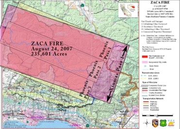
Xiomas is developing advanced high-resolution imaging instruments that will help map wildfires in greater detail to aid firefighters with coordination and safety when battling these large fires. Current wildfire imaging technology captures fire data in infrared wavelengths to map the ground temperatures and cut through the smoke, and typically operate at altitudes around 10,000 feet, which only gives a 6 mile wide field of view for each pass, which represents a limiting factor.
Xiomas’s Thermal Mapping and Measurement Sensor (TMMS) is the latest evolution of their high altitude fire mapping sensor. Designed to operate at around 40,000 feet, the Xiomas sensor captures a 16 mile wide path, resulting in triple the ground coverage in a single pass and without compromising critical resolution and data collection.
Despite operating at much higher altitudes than contemporary infrared sensors, TMMS can create an image with the same ground resolution as current technology by creating a mosaic of many smaller images and patching them together in software to create a much larger image. Xiomas’ goal is to create a more efficient airborne sensor to reduce operation costs, decrease flight time, and increase coverage to better help firefighters on the ground.
Xiomas’ technology has attracted the attention of NASA, who have funded the development and testing of a few generations of thermal mapping instruments, the WAI (Wide Area Imager), TMAS (Thermal Mapping Airborne Simulator), TBIRD (Three Band IR Detector), and now the TMMS sensors. Set to begin testing by NASA in Fall 2024 aboard their ER-2 High-Altitude Airborne Science Aircraft derived from the famous U-2 spy plane, Xiomas is hoping to expand the TMMS sensor to be integrated into satellites in the next few years.
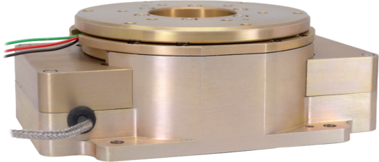
The ThinGap-designed turnkey assembly integrates one of its slotless motor with an optical encoder and bearing set into a precision aluminum housing.
At the heart of the Xiomas’s TMMS is the Across-Track Scanner, which is built around a custom motor assembly and ThinGap’s OTS LSI 75-12 Brushless DC motor. The ThinGap engineered assembly is based on a cog-free, low profile “slotless” motor integrated into a precision-machined aluminum housing, with a high resolution optical encoder, pre-loaded bearing set, and paired with a high-PWM, low-inductance controller, all of which drives a lightweight scan mirror.
The TMMS sensor has a 110 degree field of view, enabled by each 5.85 degree movement of the scan mirror, which triggers the camera to take an image. The ability to deliver a framed assembly (link to modified/custom page) based off an off-the-shelf motor kit with is another example of ThinGap’s ability to deliver an optimized, yet cost and budget effective turnkey motor assembly for rapid customer integration.
Many members of ThinGap’s team have been directly affected by the wind-driven brushfires that Southern California is famous for, so the ability to directly contribute to community safety is a matter of pride.
To learn more about Xiomas Technologies, please visit their website.